


-
在光伏和平板显示等领域, 通常采用大面积容性耦合腔室进行等离子体增强化学气相沉积. 随着腔室尺寸增大和驱动频率提高, 受驻波效应影响, 驱动电极电势幅值分布不均匀, 从而导致沉积薄膜不均匀的问题日益凸显. 针对此问题, 本文通过流体模型与传输线模型耦合, 以光伏硅基薄膜沉积中常用的硅烷氢气混合气体为研究对象, 考虑电子-中性粒子弹性碰撞, 研究了气压、气体比例和功率等参数对表面波传播以及驱动电极电势幅值分布的影响. 模拟结果与实际工艺腔室中薄膜沉积实验结果进行了对照, 验证了驱动电极电势幅值分布与薄膜厚度分布之间的对应关系. 研究表明, 在功率较低硅烷含量较高时, 表面波的径向衰减十分显著, 从而成为影响驱动电势幅值分布不均匀的主导因素. 本文还研究了调整电源馈入位置和采用多个电源馈入点来优化电势幅值分布均匀性的方法, 受表面波波长限制, 这两种方法效果有限. 而采用曲面电极能显著提升电势幅值分布的均匀性, 然而对参数设定和加工精度要求较高. 本研究不仅深化了对驻波效应作用机制的理解, 还为工业生产中解决驻波效应对薄膜均匀性的影响提供理论支撑与指导, 有望推动相关产业技术革新.
-
关键词:
- 容性耦合放电 /
- 等离子体增强化学气相沉积 /
- 驻波效应
Large-area capacitively coupled discharges are widely used in plasma enhanced chemical vapor deposition (PECVD) processes for solar cell and display manufacturing. With the increase of the chamber size and driving frequency for improving production efficiency, the non-uniformity of deposited film induced by standing wave effects becomes more serious, which deserves more attention and in-depth research. Based on a fluid model coupled with a transmission line model, the potential amplitude distribution on the powered 2 m2 electrode and the plasma characteristics in a capacitive plasma sustained in a silane/hydrogen discharge driven at 27.12 MHz are investigated. This work identifies three key control parameters: pressure, silane content, and input power, with particular emphasis on radial wave attenuation caused by electron-neutral elastic collisions. The simulation results are validated by industrial experimental results, confirming the relationship between the distributions of potential amplitude on the powered electrode and the film thickness. Two different mechanisms emerge from the analysis. Under the conditions of low silane content and high power, the surface wave radial attenuation is not significant and the surface wave wavelength variations dominate the potential amplitude distribution on the powered electrode. Conversely, in the case of high silane content and low power, significant radial attenuation of the surface wave leads to the noticeable weakening of the standing wave effect due to higher electron-neutral collision frequency. Neglecting the radial attenuation of the surface wave will result in significant deviations in the potential amplitude distribution on the powered electrode as shown in the following figure. Strategies such as adjusting power input positions or using multiple power input are studied to improve uniformity, but the improvements are still limited. Although it requires strict parameter control and machining precision, the shaped electrode demonstrates remarkable uniformity improvement of the potential distribution. In the future work, it is necessary to further analyze the influence of the standing wave effects on the radial distributions of electron, ions, and neutral radicals under complex conditions, such as different chamber structures, gas flows, and temperature distributions, as well as the influence on the quality of deposited films. This will enable a more comprehensive and accurate study of standing wave effects, providing support and guidance for solving real industrial problems. 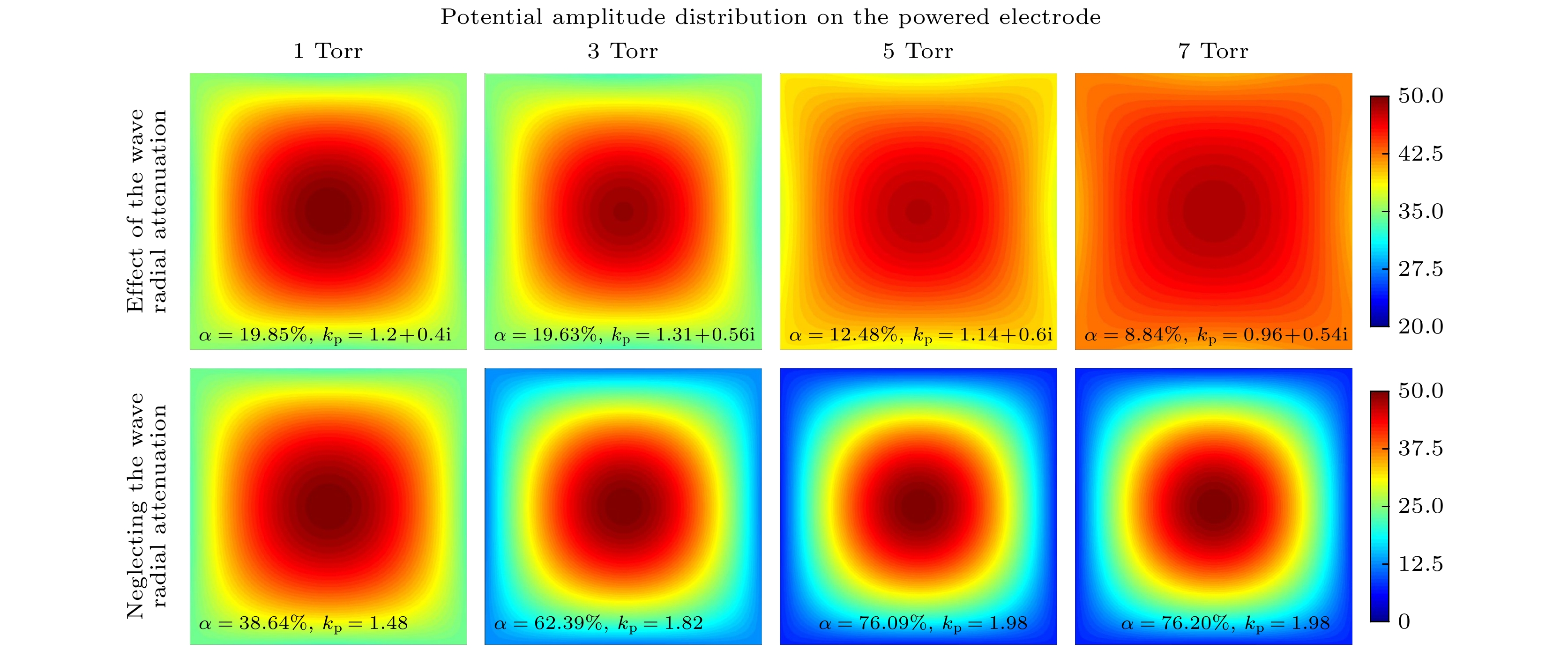
-
Keywords:
- capacitive coupling discharge /
- plasma enhanced chemical vapor deposition /
- standing wave effect
[1] [2] [3] [4] [5] [6] [7] [8] [9] [10] [11] [12] [13] [14] [15] [16] [17] [18] [19] [20] [21] [22] [23] [24] [25] [26] [27] [28] [29] [30] [31] [32] [33] [34] [35] [36] [37] [38] [39] [40] [41] -
序号 反应 阈值能/eV 系数[38,39]
/(cm3·s–1)R1 SiH4+e→SiH4+e — cal R2 SiH4+e→$ {{\mathrm{S}}{\mathrm{i}}{\mathrm{H}}}_{3}^{+} $+H+2e 11.9 cal R3 SiH4+e→$ {{\mathrm{S}}{\mathrm{i}}{\mathrm{H}}}_{3}^{-} $+H 5.7 cal R4 SiH4+e→$ {{\mathrm{S}}{\mathrm{i}}{\mathrm{H}}}_{2}^{-} $+2H 5.7 cal R5 SiH4+e→SiH3+H+e 8.3 cal R6 SiH4+e→SiH2+2H+e 8.3 cal R7 H2+e→H2+e — cal R8 H2+e→2H+e 8.9 cal R9 H2+e→$ {{\mathrm{H}}}_{2}^{+} $+2e 15.4 cal R10 Si2H6+e→Si2$ {{\mathrm{H}}}_{4}^{+} $+2H+2e 10.2 cal R11 Si2H6+e→SiH3+SiH2+H+e 7.0 cal R12 $ {{\mathrm{S}}{\mathrm{i}}{\mathrm{H}}}_{3}^{+} $+ $ {{\mathrm{S}}{\mathrm{i}}{\mathrm{H}}}_{3}^{-} $→2SiH3 — 1.0×10⁻⁸ R13 $ {{\mathrm{S}}{\mathrm{i}}{\mathrm{H}}}_{3}^{+} $+$ {{\mathrm{S}}{\mathrm{i}}{\mathrm{H}}}_{2}^{-} $→SiH3+SiH2 — 1.0×10⁻⁸ R14 $ {{\mathrm{H}}}_{2}^{+} $+$ {{\mathrm{S}}{\mathrm{i}}{\mathrm{H}}}_{3}^{-} $→SiH3+H2 — 1.0×10⁻⁸ R15 $ {{\mathrm{H}}}_{2}^{+} $+$ {{\mathrm{S}}{\mathrm{i}}{\mathrm{H}}}_{2}^{-} $→SiH2+H2 — 1.0×10⁻⁸ R16 Si2$ {{\mathrm{H}}}_{4}^{+} $+$ {{\mathrm{S}}{\mathrm{i}}{\mathrm{H}}}_{3}^{-} $→SiH3+H2 — 1.0×10⁻⁸ R17 Si2$ {{\mathrm{H}}}_{4}^{+} $+$ {{\mathrm{S}}{\mathrm{i}}{\mathrm{H}}}_{2}^{-} $→3SiH2 — 1.0×10⁻⁸ R18 SiH4+$ {{\mathrm{H}}}_{2}^{+} $→$ {{\mathrm{S}}{\mathrm{i}}{\mathrm{H}}}_{3}^{+} $+H2+H — 1.0×10⁻⁸ R19 SiH4+H→SiH3+H2 — 1.2×10⁻¹² R20 Si2H6+H→H2+Si2H5 — 7.0×10⁻¹² R21 Si2H6+H→SiH3+SiH4 — 3.5×10⁻¹² R22 SiH3+SiH3→SiH4+SiH2 — 1.5×10⁻¹⁰ R23 SiH2+H2→SiH4 — 2.7×10⁻¹⁴ R24 SiH2+SiH4→Si2H6 — 2.3×10⁻¹¹  下载: 导出CSV
p/Torr $ {n}_{{\mathrm{e}}} $/(1015 m–3) $ {d}_{{\mathrm{s}}{\mathrm{h}}} $/cm $ \boldsymbol{\delta } $/cm $ {\upsilon }_{{\mathrm{e}}{\mathrm{n}}} $/(1010Hz) $ {\varepsilon }_{{\mathrm{e}}{\mathrm{f}}{\mathrm{f}}} $ 1 5.98 0.20 6.88 0.36 4.02+0.46i 2 19.56 0.13 3.80 0.72 6.08+0.68i 3 37.57 0.08 2.74 1.08 9.30+1.29i 4 55.81 0.06 2.25 1.44 12.65+2.20i
下载: 导出CSV
p/Torr $ {n}_{{\mathrm{e}}} $/(1015 m–3) $ {d}_{{\mathrm{s}}{\mathrm{h}}} $/cm ${\delta } $/cm $ {\upsilon }_{{\mathrm{e}}{\mathrm{n}}} $/(1010 Hz) $ {\varepsilon }_{{\mathrm{e}}{\mathrm{f}}{\mathrm{f}}} $ 1 2.40 0.15 10.86 0.59 3.99+3.02i 3 7.72 0.10 6.06 1.77 4.33+4.53i 5 9.12 0.08 5.57 2.94 2.88+4.25i 7 8.70 0.08 5.70 4.12 1.94+3.18i
下载: 导出CSV
-
[1] [2] [3] [4] [5] [6] [7] [8] [9] [10] [11] [12] [13] [14] [15] [16] [17] [18] [19] [20] [21] [22] [23] [24] [25] [26] [27] [28] [29] [30] [31] [32] [33] [34] [35] [36] [37] [38] [39] [40] [41]


 下载:
下载:


计量
- 文章访问数: 833
- PDF下载量: 68
- 被引次数: 0